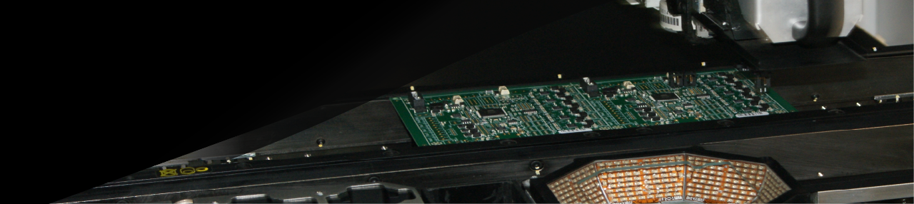
UltiMachine
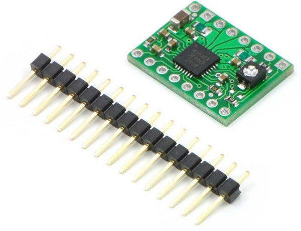
Pololu A4988 Stepper Driver Kit
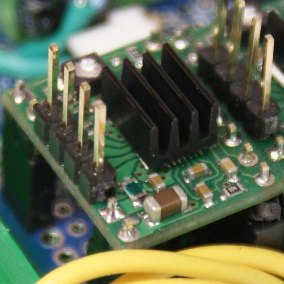
Kit includes Pololu A4988 Stepper Driver and 1x16-pin breakaway 0.1" male header.
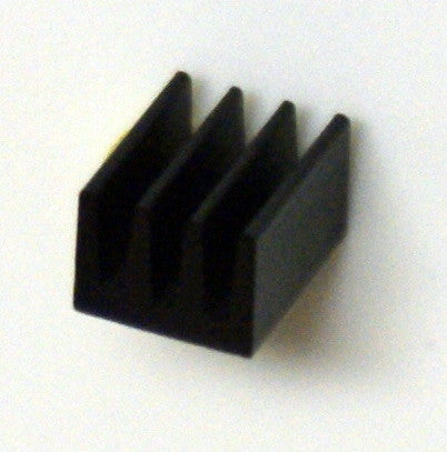
We also offer for an additional cost, an option to include one (1) heatsink w/ adhesive with your kit, and/or the option to have UltiMachine assemble the kit for you.
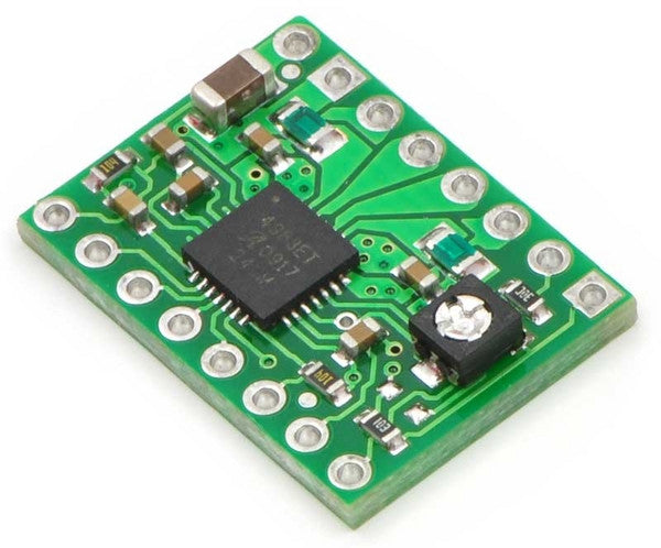
The A4988 stepper motor driver carrier is a breakout board for Allegro’s easy-to-use A4988 microstepping bipolar stepper motor driver and is a drop-in replacement for the A4983 stepper motor driver carrier. The driver features adjustable current limiting, overcurrent protection, and five different microstep resolutions. It operates from 8 – 35 V and can deliver up to 2 A per coil.
Note: This board is a drop-in replacement for the original Pololu A4983 stepper motor driver carrier. The newer A4988 offers overcurrent protection and has an internal 100k pull-down on the MS1 microstep selection pin, but it is otherwise virtually identical to the A4983.
The A4988 stepper motor driver carrier is a breakout board for Allegro’s easy-to-use A4988 microstepping bipolar stepper motor driver. The driver features adjustable current limiting and five different microstep resolutions. The driver operates from 8 – 35 V and can deliver up to 2 A per coil.
- Simple step and direction control interface
- Five different step resolutions: full-step, half-step, quarter-step, eighth-step, and sixteenth-step
- Adjustable current control lets you set the maximum current output with a potentiometer
- Intelligent chopping control that automatically selects the correct current decay mode (fast decay or slow decay)
- Over-temperature thermal shutdown, under-voltage lockout, and crossover-current protection
- Short-to-ground and shorted-load protection
The A4988 stepper motor driver carrier comes with one 1x16-pin breakaway 0.1" male header. The headers can be soldered in for use with solderless breadboards or 0.1" female connectors.
Using the driver
Power connections
The driver requires a logic supply voltage (3 – 5.5 V) to be connected across the VDD and GND pins and a motor supply voltage of (8 – 35 V) to be connected across VMOT and GND. These supplies should have appropriate decoupling capacitors close to the board, and they should be capable of delivering the expected currents (peaks up to 4 A for the motor supply).
Step (and microstep) size
Stepper motors typically have a step size specification (e.g. 1.8° or 200 steps per revolution), which applies to full steps. A microstepping driver such as the A4988 allows higher resolutions by allowing intermediate step locations, which are achieved by energizing the coils with intermediate current levels. For instance, driving a motor in quarter-step mode will give the 200-step-per-revolution motor 800 microsteps per revolution by using four different current levels.
The resolution (step size) selector inputs (MS1, MS2, MS3) enable selection from the five step resolutions according to the table below. MS2 and MS3 have internal 100kΩ pull-down resistors, but MS1 does not, so it must be connected externally. For the microstep modes to function correctly, the current limit must be set low enough (see below) so that current limiting gets enganged. Otherwise, the intermediate current levels will not be correctly maintained, and the motor will effectively operate in a full-step mode.
MS1 MS2 MS3 Microstep Resolution
Low Low Low Full step
High Low Low Half step
Low High Low Quarter step
High High Low Eighth step
High High High Sixteenth step
Control inputs
Each pulse to the STEP input corresponds to one microstep of the stepper motor in the direction selected by the DIR pin. The chip has three different inputs for controlling its many power states: RST, SLP, and EN. Please note that the RST pin is floating; if you are not using the pin, you can connect it to the adjacent SLP pin on the PCB.
Current limiting
To achieve high step rates, the motor supply is typically much higher than would be permissible without active current limiting. For instance, a typical stepper motor might have a maximum current rating of 1 A with a 5Ω coil resistance, which would indicate a maximum motor supply of 5 V. Using such a motor with 12 V would allow higher step rates, but the current must actively be limited to under 1 A to prevent damage to the motor.
The A4988 supports such active current limiting, and the trimmer potentiometer on the board can be used to set the current limit. One way to set the current limit is to put the driver into full-step mode and to measure the coil current without clocking the STEP input. The measured current will be 0.7 times the current limit (since both coils are always on and limited to 70% in full-step mode). Please note that the current limit is dependent on the Vdd voltage.
Another way to set the current limit is to measure the voltage on the “ref” pin and to calculate the resulting current limit (the current sense resistors are 0.05Ω). The ref pin voltage is accessible on a via that is circled on the bottom silkscreen of the circuit board. See the A4988 datasheet for more information.
Power dissipation considerations
The A4988 driver IC has a maximum current rating of 2 A per coil, but the chip by itself will overheat at lower currents. The actual current you can deliver depends on how well you can keep the stepper motor driver cool. The carrier’s printed circuit board is designed to draw heat out of the A4988 chip, but to supply more than approximately 1 A per coil, a heat sink is required.
Please note that measuring the current draw at the power supply does not necessarily provide an accurate measure of the coil current. Since the input voltage to the driver can be significantly higher than the coil voltage, the measured current on the power supply can be quite a bit lower than the coil current (the driver and coil basically act like a switching step-down power supply). Also, if the supply voltage is very high compared to what the motor needs to achieve the set current, the duty cycle will be very low, which also leads to significant differences between average and RMS currents.
More information on Pololu electronics at Pololu and RepRap.
Heat Sink 6.3mm X 4.8mm
Thermal Resistance: 87 degrees Celsius
Width: 6.3mm
Height: 4.8mm
Length: 8mm
Heat Sink Material: Aluminum
Body Plating: Black Anodized
Mounting Type: Adhesive
We throw in a little piece of Akasa heat sink tape to mount it to your component.